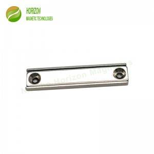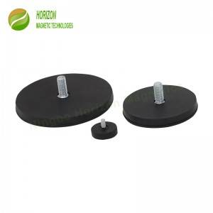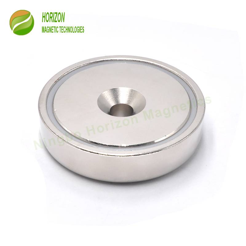

For the countersunk pot magnet, the countersunk hole of the pot magnet is machined from the surface of the Neodymium disc magnet to the interior of the magnet, Neodymium countersunk magnet. It is common in the field of mechanical manufacturing and construction to install bolts or other connecting parts. The countersunk hole can avoid the protrusion of the screw and ensure the flatness of the installation plane. The processing method of countersunk hole includes drilling and counterbore processing. The counterbore is divided into flat bottom counterbore and cone counterbore. No matter what kind of counterbore, it is necessary to first drill the main through hole with a drill bit, and then select different tools for counterbore processing according to the countersink shape. It is necessary to mill the counter bore by end milling cutter on the basis of drilling. It is necessary to countersink on the drilled hole with a larger drill bit. In the process of counterbore machining, the work piece should be positioned once to ensure the coaxiality of the hole and the counterbore.
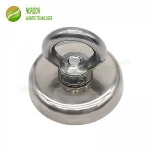
Due to this simple structure, it’s very simple to bolt the countersunk screw through the countersunk pot magnet hole. It’s widely seen in industrial, warehouse, or even daily use.
1.Quality First: genuine Neodymium magnet to extend the lifetime
2.More sizes available to save tooling cost and then price for customers
3.Standard sizes in stock and available for immediately delivery
4.Custom-made solutions available upon request
| Part Number | D | d1 | d2 | H | Force | Net Weight | Maximum Operating Temperature | ||
| mm | mm | mm | mm | kg | lbs | g | °C | °F | |
| HM-A16 | 16 | 3.5 | 6.5 | 5.0 | 6 | 13 | 5.5 | 80 | 176 |
| HM-A20 | 20 | 4.5 | 8.5 | 7.0 | 11 | 24 | 12 | 80 | 176 |
| HM-A25 | 25 | 5.5 | 10.5 | 8.0 | 20 | 44 | 21 | 80 | 176 |
| HM-A32 | 32 | 5.5 | 10.5 | 8.0 | 32 | 70 | 37 | 80 | 176 |
| HM-A36 | 36 | 6.5 | 12.0 | 8.0 | 42 | 92 | 45 | 80 | 176 |
| HM-A42 | 42 | 6.5 | 12.0 | 9.0 | 66 | 145 | 72 | 80 | 176 |
| HM-A48 | 48 | 8.5 | 16.0 | 11.5 | 80 | 176 | 125 | 80 | 176 |
| HM-A60 | 60 | 8.5 | 16.0 | 15.0 | 112 | 246 | 250 | 80 | 176 |
| HM-A75 | 75 | 10.5 | 19.0 | 18.0 | 162 | 357 | 465 | 80 | 176 |